Form of installation 1
An installation with junction boxes
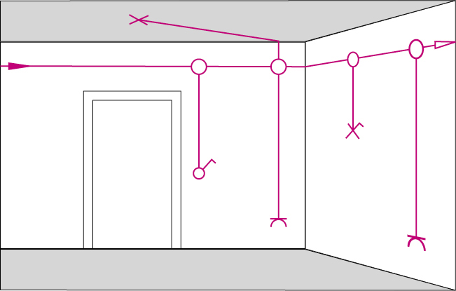
When installing with a junction box (1), the cables are routed horizontally along the upper wall area. A junction box with a ceiling clearance of approx. 30 cm is placed at each branch in the vertical direction. From there, the switches or sockets to be installed below are wired. This form is seldom used today because the installation effort and material input is too high and renovation work is required in case of repair.
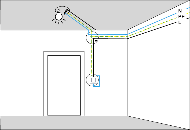
The wiring diagram with junction boxes (2) In an effective circuit diagram for this type of installation, it becomes clear that the respective function of installations such as lamps, switches or sockets is defined in the junction box. This includes circuit types such as off-switching, change-over switching, cross-switching, series switching or push-button switching. Repairs or changes therefore require an intervention in the junction box.
Form of installation 2
An installation in switch boxes
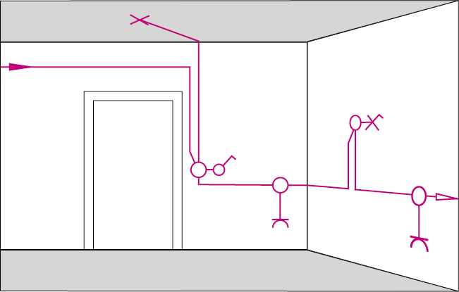
When installing with switch boxes (1), the cables are routed directly from one switch box to the next and clamped in these. For this purpose, switch boxes with a greater box depth (min. 46 mm, better 61 mm) are used to provide sufficient space for clamping incoming and outgoing cables. If the switch or socket insert is removed from the switch box, the connecting terminals of the cables behind it are easily accessible. This has the advantage that changes in the installation can be made quickly and without painting.
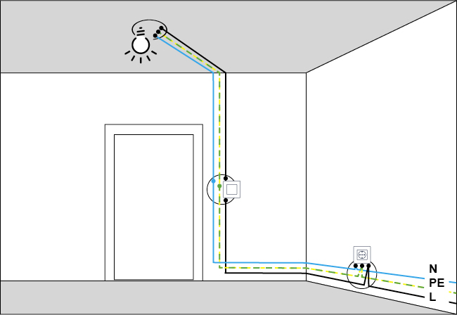
Active circuit diagram in switch boxes (2)
The wiring diagram for this type of installation shows that - in contrast to junction boxes - the circuit type is wired in the freely accessible switch box itself.
Form of installation 3
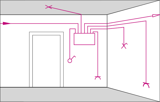
An installation with one distribution box
If a "distribution box" is used in the installation, each luminaire and switch box is connected to this distribution box with its own cable. Distribution boxes are usually placed centrally within an office unit, e.g. in the corridor, in order to arrange supply lines in the shortest possible way and clearly.
This type of installation is mainly used in administrative and commercial buildings.
Installation zones for power cables
Learn more about where power cables are routed in the walls.
Switch-off, alternating and series circuits
Here you will find detailed illustrations of disconnection, alternating and series circuits.
Comparing wireless systems
Compare the smart home systems Philips Hue, Casambi, EnOcean and Tuya in our overview.
Retrofit switches
Learn how to retrofit the Hidden Socket | Versteckdose® on existing wired switches.

